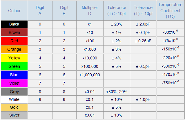


The five band capacitor shown in the above figure value can be determined using the capacitor color code chart discussed above. Capacitance Calculation using Capacitor Color Code Consider a metalized polyester capacitor as shown in the below figure which consists of five bands.
#0.05 UF CAPACITOR CODE CHART HOW TO#
Let us discuss about a few examples to know how to find capacitor value using capacitor color code. Hope, this article given a basic information regarding the capacitor color code. In few capacitor color code representation ‘R’ is used as decimal, i.e., ‘4R7’ is used instead of ‘4.7’. In general, ceramic capacitors are labeled and if the number is less than one, then capacitor value is picofarads and if the number is greater than one, then the capacitor value is microfarads. Third column indicates the tolerance value (sub-columns for above and below 10pf) of the capacitor, fourth column indicates the temperature coefficient. The capacitor color code for ceramic capacitors is shown in the above figure in which first column represents different types of colors, the second column represents the value indicated by a specific color. The fifth band represents the working voltage of the capacitor (example 250V-red and 400V-yellow). The fourth band represents the tolerance value which is usually indicated by black-20%, white-10, and green-5%. Second band represents a second number from the chart and the third band represents the number of zeros. If the capacitor is having five bands, then the first band represents the first number of capacitor color code table shown in the above figure. In every capacitor, practically there will be small leakage current which is zero in ideal capacitors. The voltage (maximum) up to which the capacitor can withstand (before dielectric breakdown) is called as working voltage of the capacitor and capacitor voltage color code is represented in below table. The value is represented on the capacitor by using capacitor color code or directly. Additional fourth or color bands thereon represent various things for various types of capacitors. If we consider a four color band capacitor, then the first and second colors marked on the capacitor represents the value of the capacitor and the third color band represents the decimal multiplier in picofarads. In general, four or more than four colors or dots are used to mark capacitors.

To understand about capacitor color code, primarily we must know various parameters of capacitors such as capacitor value, tolerance of capacitor, working voltage of the capacitor, and leakage current of the capacitor. The capacitor calculator can be used to find the value of various types of capacitors. There are various types of capacitors such as ceramic disc, ceramic tubular, button mica molded mica, dipped mica, air trimmers, paper and film capacitors which are represented using various types of capacitor color codes and capacitor codes. Thus, decimal points are mostly avoided and Pico (p) or Nano (n) are used to represent decimal point number’s weight and position. In the capacitor color code system, if the capacitance value consists of a decimal point, then it is not easy to read the capacitance value which results in misreading. Similarly, the tolerance or voltage value or capacitance values are represented on the capacitor’s body using alphanumeric characters. The electronic color code systems are various types in which, well known resistor color code system is used for identifying the value of resistors.


 0 kommentar(er)
